Extrude
The fastest way to get a 3d model from your design is to use the 3d setting of the layers. These 3d settings will be used to extrude the corresponding layers and add it to the 3d view. After a layer setup you just need to trigger the 3d rendering. There are different ways for the rendering:
- RenderAll - all visible shapes of the current cell are displayed
- RenderView - only the current view of the current cell is displayed
- RenderSelect - selected elements of the current cell are rendered
3d Layer Settings
Prior to using this way a setup had to be performed. A thickness and level of any layer had to be defined. This setup can be done in different ways:
- by the layer manager (in the layer menu or in the 3d doch window),
- via the layer properties ( in the context menu of the layer buttons),
- by a cross section drawing (in the 3d dock windows).
The simplest way may be the last one: draw a cross-section view of your technology in a separate cell/library and press the setup from cross-section button. All required information (thickness and level) is extracted from the cross-section. Afterwards select your cell and activate one of the render functions.
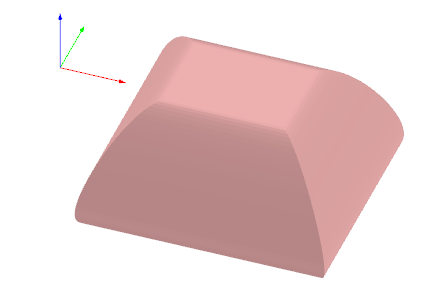
Extrude (manual)
Alternative to the automated 3d generation a manual generation is possible the the Extrude section of the 3d dock you can exrude a layer manual and add it to the 3d editor.
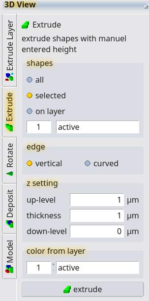
In this way additional options are available. Curved edges can be generated. The edge contur had to be defined by a path element.
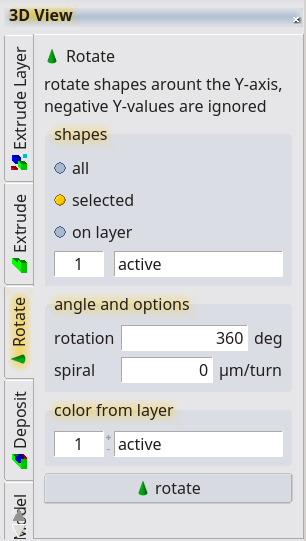
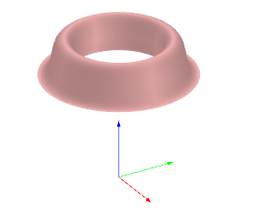
Rotation
Rotating object can be created the the rotate feature. The choosen shapes are rotatedaround the y-axis. Shape with negative y value will be cut away. An additional spiral value can be added. The color from the target layer is use in the 3d view.
© 2026 juspertor GmbH