Example
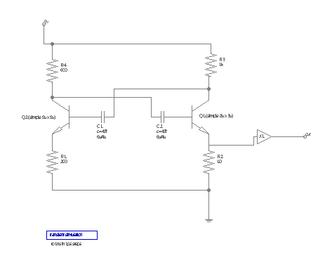
Lets have a look at an example: How the LT-Spice netlist for this schematic is created:
Netlist setup for LT-Spice from the Setup dialog:
*ltspice $filename generated by the LayoutEditor (www.LayoutEditor.net)
$groundnode(0)
*start of netlist
$netlist(spice)
*LTspice specific part
$netlist(ltspice)
*end of netlist

*required models
$model(spice)
On the first line the expression $filename will be replaced by the name for the circuit. So the output for this line will look like *ltspice /home/thies/example.les generated by the LayoutEditor (www.LayoutEditor.net). The second line will not output anything, but any occurance of a node connected ground will be outout with 0.
$netlist(spice) will be replaced by a list with the spice netlist for all used components. So the resistor R1 will be replaced by $devicename $node(A) $node(B) $value. From this expression $deviename is replaced by R1, $node(A) is replace with the node name connected to port A, port B is connected to ground so it is replaced with the ground nade name 0. Finally $value is replaced by the value of parameter value. The resulting output will be R1 Node_6 0 200.
All other components are processed in an identical way. Let's have a look at the transistor Q1. In the component setup the spice netlist is defined as .model npn$devicename NPN( IS=$IS BF=$BF ) $devicename $node(C) $node(B) $node(E) 0 npn$devicename.
After replacing $devicename, $IS, $BF, $node(C), $node(B) and $node(E) the output will be .model npn_Q1 NPN( IS=2.4u BF=204.24 ) Q1 Node_4 Node_8 Node_9 0 npn_Q1.
To resulting list for $netlist(spice) is :
XL1 VSS VDD Node_2 out BUF_X1
.model npn_Q2  NPN( IS=2.5u BF=204 )
Q2 Node_3 Node_7 Node_6 0 npn_Q2
.model npn_Q1  NPN( IS=2.4u BF=204.24 )
Q1 Node_4 Node_8 Node_9 0 npn_Q1
R4 5v Node_3 600
R3 5v Node_4 1k
R2 Node_9 0 10
R1 Node_6 0 200
C2 Node_3 Node_8 48f
C1 Node_7 Node_4 48f
The simulation component does not have any output defined for the spice netlist, so it will not appear. However is has an output defined for ltspice. So it will result an output for $netlist(ltspice): .tran 1p 1n.
The line $model(spice) will work similarily to the netlist(...) command, but it will only output once per component type. Even if there are multiple components using the include file with the spice models, it is only printed once.
The final netlist:
*ltspice /home/thies/example.les generated by the LayoutEditor (www.LayoutEditor.net)

*start of netlist
XL1 VSS VDD Node_2 out BUF_X1
.model npn_Q2  NPN( IS=2.5u BF=204 )
Q2 Node_3 Node_7 Node_6 0 npn_Q2
.model npn_Q1  NPN( IS=2.4u BF=204.24 )
Q1 Node_4 Node_8 Node_9 0 npn_Q1
R4 5v Node_3 600
R3 5v Node_4 1k
R2 Node_9 0 10
R1 Node_6 0 200
C2 Node_3 Node_8 48f
C1 Node_7 Node_4 48f

*LTspice specific part
.tran 1p 1n

*end of netlist

*required models
.include /home/thies/layout/library/openCellLibrary/spicemodel.sp© 2026 juspertor GmbH