Basics
A schematic is a collection of sheets. The SchematicEditor displays just one sheet of this collection at a time. Changing the displayed sheet is possible via the combo box control in the tool bar of the SchematicEditor. Each sheet consists of components (=devices), connections between the components and non functional parts.
Non Functional Parts
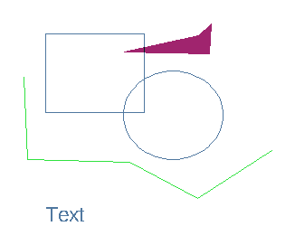
Non functional parts are not considered in the layout or in the simulation. They are just used for information or administrative purpose. It can be a drawing frame or creator name. Non functional parts in the SchematicEditor are:
- Arc
- Circle
- Line
- Polygon
- Rectangle
- Text
The color can be set for each non functional part independently and can individually be adjusted. Changing the color is done via the right click menu of the EditItem feature. Non functional elements are also needed to draw symbols for components. A symbol of a component consists only of non functional shapes, Ports and BusPorts. A symbol is drawn in the same drawing area as the schematic and can be assigned to a component by the EditComponent feature.
Connections
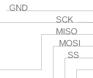
Connections connects the ports of a component with other components or via the Port element to an external connection. A connection can be an electrical connection or any other connection. It can be a single connection or a bundle of connections in a bus. A single connection is drawn in the schematic with the Wire feature. A Wire should not be confused with a Line as a line is non functional. All wires are displayed in the same color. Modifying the color can be globally done in the Setup Dialog. A connection of two wires in the schematic is displayed with a small dot. Two crossing wires without a dot are not connected. A Wire can be named with the LabelNode feature. The name will be used for the NetlistGeneration as well for the schematic driven layout. A Bus is a bundle of connections. It is displayed in another color than a Wire and also can be globally adjusted in the Setup Dialog. A wire connected to a bus needs to be named. Any connection to sub schematics or external connections are realized by Ports and Bus Ports.
- Wire
- Bus
- Port
- BusPort
- LabelNode
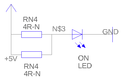
Components
A component or device is the functional part of a schematic. Components are managed in libraries which contains all component related information. This includes parameters of the component, symbol, ports, netlist and simulation data, layout information, and extraction information. Opened component libraries are displayed next to the schematic drawing. To place a component just click it in the component list and place it. The component will be displayed in the schematic with its symbol and a label. The label format is also included in the component library and can be adjusted as any other data of a component with the Edit Component feature. Parameters for the individual component placement can be adjusted with the Edit Item feature.
Hierarchy
The SchematicEditor supports hierarchy. In a hierarchical circuit a schematic sheet is used as a component in another schematic sheet. The as component used circuit is also called subcircut. Multi level hierarchy is possible. So a schematic with a subcircuit as component can be a subcircuit in a further schematic. A subcircuit is displayed as a symbol in the upper level schematic. A subcircuit is created within the LayoutEditor with the Use As Component feature. Calling that feature will add a -internal- library to the library list and create a component made from the current displayed schematic. A symbol will be created automaticly. To adjust the symbol, draw it in a new sheet by just using non-functional parts and ports. Set the symbol to the component by the Edit Component feature.
© 2026 juspertor GmbH