Layer and Shapes
Layer
A layer is a logical grouping of graphical elements that can be manipulated as a single unit. Layers are used to organize and manage the different components of a drawing or design. Each layer can contain different types of elements, such as pathes and text. Layers can also have different properties, such as color, line style, and visibility; each can be controlled independently.
Some of the main benefits of using layers include:
- Organization: Layers allow you to keep your drawings organized by separating different elements into different layers. This makes it easy to find, edit, and manage the different components of your design.
- Visibility: Layers can be turned on or off individually, making it easy to hide or show specific parts of your design without affecting the rest of the drawing.
- Editing: Layers allow you to edit specific parts of your design without affecting the rest of the drawing. For example, you can edit one layer without affecting the rest of the design.
- Printing: Layers can be used to control which elements are printed, making it easy to print only the parts of your design that are relevant.
Each shape of a design belongs to a layer. Shapes on different layers are displayed differently. For each layer a set of data is stored:
- layer number
- layer name
- color
- fill style
- shortcut
- visibility
- 3d information
- further technology information
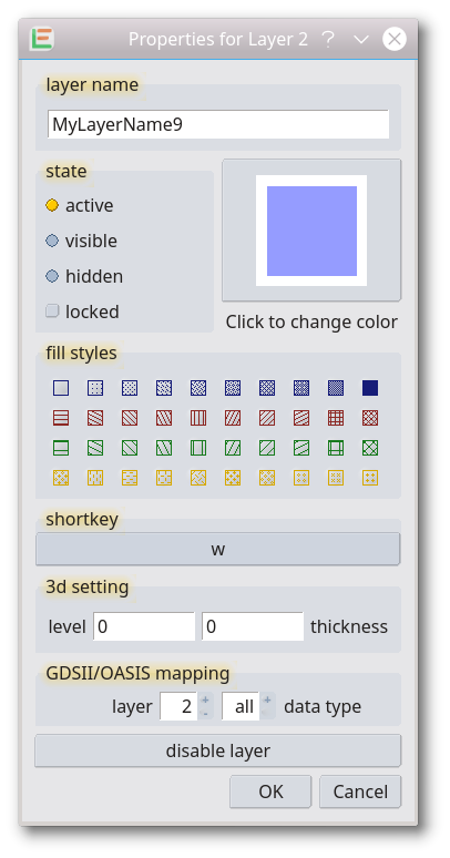
Layer Properties
is a dialog to edit a single layer. It can be opened with a control+shift left-click from the layer dock window. In the dialog, all settings of a single layer can be adjusted. Some optional settings will be displayed after pressing the little + in the lower left of the dialog.
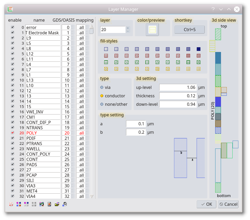
Layer Manager
is a dialog with all settings for all layers. All settings can be adjusted. Some additional features like loading the setting from other formats or generating a macro with the current layer setting will be displayed after pressing the little + in the lower left of the dialog.
Layer Shortcuts
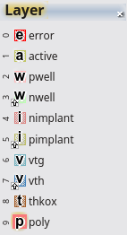
Setup the layers quickly using shortcuts. These shortcuts are combination shortcuts. With the first key, the function is activated. With the following key(s) the layer is selected. The shortcuts of the layer can be set via Layer Properties, Layer Manager or the command line. It is possible to reuse an existing shortcut for the layer-shortcut. After pressing the first shortcut, the layer shortcuts will be displayed in the layer list.
Set Active Layer (shortcut: 1):
Select the active layer via a shortcut. The key pressed after activation of this function will determine the active layer. The layer shortcuts have to be set up prior.
Layer Visibility toggle (shortcut: 2):
The visibility of layers is changed via the layer shortcut. The key pressed after activation of this function will determine the visibility. The layer shortcuts have to be set up prior. Leave this function via the Esc key.
Hide Other Layers (shortcut: 3):
Hide other layers via the layer shortcut. The key pressed after activation of this function will determine the visibility. The layer shortcuts have to be set up prior. Leave this function via the Esc key.
Show All Layers (shortcut: 4):
Make all layers visible via shortcut.
Database Units and Userunits
Databaseunits
All coordinates of any design are saved as an integer. The database unit is the distance represented by 1 and therefore the smallest possible distance in the design. All coordinates can only be a multiple of the database unit. If you change the database units within the setup dialog, you can select whether the elements are adopted (=same absolute dimensions) or not modified (=same integer value=scaled by the change of database units).
Userunits
Userunits is the unit used to display any coordinate, length, dimension, etc. to the user. It is specific to a design (and not a global setting). Some file formats include this setting and also include the database units. Loading such a file will change both userunits and database units.
Shapes
In the LayoutEditor as well as in the GDSII file format four kinds of shapes exist:
Path
A multi segment line, having a width and a setting for its caps.
Box
A rectangle horizontal orientated.

Polygon
A polygon

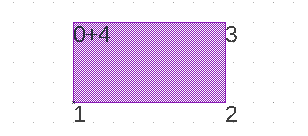
Storage of Polygons
The LayoutEditor is, like other CAD programs, a vector program. This means that every shape is saved as a sequence of vectors. So a rectangular polygon consists of 5 coordinates with the last one identical with the first one. In this case inside and outside of the polygon is clearly declared. This is important as some algorithms require size adjustments. Furthermore, the LayoutEditor will sort the points automatically in counterclockwise order.
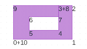
Polygons with Holes
A polygon is a sequence of vectors describing the outer contour. To define a hole inside a polygon, a link will be added from the outer contour to the inner hole contour. In this way, a polygon keeps still a single sequence of vectors. To keep polygon processing simple it is recommended that all links between the outer contour and an inner contour are vertical or horizontal.
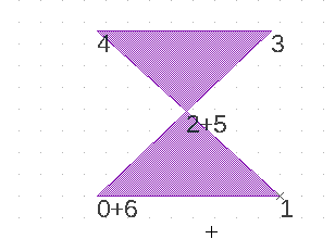
Selfintersecting Polygons
Already with a five-point polygon, you may get trouble. In this example, it is still clear what is inside and outside the polygon. A filling can be calculated correctly. However, if you try to adjust the size of this polygon by moving the existing points, you may not be able to maintain the desired shape. Also, it is not possible to sort the points in counterclockwise order.
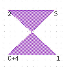
The next example is a little more complex. In this polygon, there is an area that is surrounded twice. It is not clearly defined if this area is part of the polygon or not. Different software will handle it differently and some unable to handle it at all.
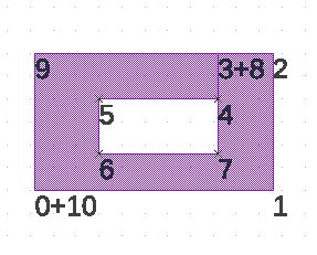
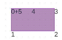
The two examples show that it is important to avoid self-intersecting polygons. The LayoutEditor will help you to do so. If enabled in the setup (shapes/general/polygon checks), it automatically detects self-intersecting polygons and converts them to non-problematic polygons. The two examples will be converted like this:
Not needed Points
Even simple polygons can have points that have no effect. These unneeded points can be a result of a prior operation. The LayoutEditor will detect these points and remove them if enabled in the setup (shapes/general/polygon checks)
Text
A text element with a width and alignment. In case of a negative width the text will be displayed in a zoom independend width in pixel.

Cells and References
Any shape belongs to a cell. So a cell is a set of shapes. A design may contain several cells. A cell can also contain references to another cell. In this case, at the position of the reference, all shapes of the referred cell are displayed. A cell can be referred many times. A repeating structure need only be created once and then referred multi times. This reduces the storage space and makes it easier to handle it. This method is called hierarchical design.
CellArrays
Next to simple references arrays of references exist. A cell array reference is a repeating reference in 1 or 2 dimensions with constant spacing.
Datatype and Element Attributes
In some file formats, additional information can be stored. For the MEMS/IC design, two kinds of information can be used: datatype (available in GDSII, OASIS, OpenAccess) and element attributes (available in GDSII). This information can be viewed/modified via the Properties Dialog. But if not used in the current design, they are hidden. To show it, press the little + in the lower-left corner in each property dialog.
Datatype
A datatype is an additional number that can be stored with each primitive element (path, box, polygon, text). It is commonly used in two areas. First, it is used in e-beam exposure of photomasks (only in sharp beam system, not in Gaussian beam systems). Different exposure energy is needed for each element to achieve an exact image. The datatype field is used to store the exposure energy. The other application is when the datatype is used is an extension of layers. The early layout systems had a hard restriction on the number of layers. To increase the number of layers the datatype was used and allowed for a more exact description of an element. It describes whether the element is part of a conductor, capacitor, or just a label. For the last application, it may be interesting to split different datatypes onto different layers. This is supported by the layout editor. Activate it via the Setup Dialog and configure it via the Layer Manager.
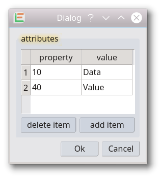
Attributes
Besides the datatype, each element can have an unlimited number of attributes. Attributes are a combination of an attribute type (normally a number) and a value (a free text). Attributes also exist for cell reference where no datatypes are possible. Attributes are rarely used. The LayoutEditor used it to store some information for the netlist driven layout.
© 2026 juspertor GmbH