SkyWater Open Source PDK
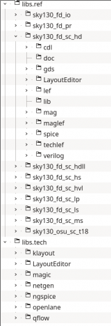
The SkyWater Open Source PDK is a collaboration between Google and SkyWater Technology Foundry to provide a fully open source Process Design Kit and related resources, which can be used to create manufacturable designs at SkyWater’s facility. The PDK can be downloaded on GitHub and converted to a so called Open-PDKs format with Open-PDKs. That format is the requirement to use it with the LayoutEditor. The file tree of the correct format should look like this:
For their convience a part of this PDK is included in LayoutEditor package. This high density standard cell library can be used straight ahead. The next chapter Installation is only required, if the other part of the SkyWater PDK is required as well. The PDK will work on all supported platforms (Windows, Linux, Mac).
Installation
SkyWater Open Source PDK is supported with LayoutEditor release 20201217 or newer. The high density lstandard cell library is included in any LayoutEditor package and no further installation is required.The in this part described installation is only required in case the full PDK is required.
To use the full Skywater PDK with the LayoutEditor, the LayoutEditor related part of the PDK needs to be added to the PDK in the OpenPDKS format (see above). These folders are part of the shipped part of the PDK inside the LayoutEditor package. Just copy and paste the folder with its contents to your full version of the PDK. The library can then be opened in the SchematicEditor with the addLibrary in the components subwindow. Just point to the .lel file of the PDK.
Usage/Setup
Part of the added file to the PDK is the file autoLayerMacro.layout. It is located under libs.tech/LayoutEditor. This macro will perform any required setup. This includes a setup of a layer mapping. The SkyWater PDK puts vias and wires on the same GDS layer. For a layer tracing inside the LayoutEditor it is required to map these shapes on different LayoutEditor layers. This mapping is one of the setup tasks performed by the macro and it is very important that this setup is done before any design is loaded. So it is highly recommend that this setup macro is executed any time the LayoutEditor is loaded to ensure that anything is setup correctly. This can automaticly be archieved by adding a copy of that macro insode your project folder and starting the LayoutEditor with:
cd path/to/your/project/folder
layout -a
The -a option makes the LayoutEditor to look for a autoLayerMacro.layout file inside the working folder and loads it automaticly.
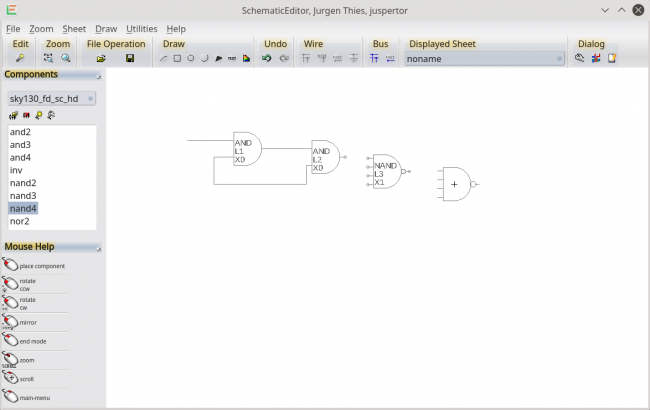
Schematic
After the setup any supported sub-library is listed in the Components window of the SchematicEditor and can be used as any other shipped library.
Place&Route
After the schematic is created a fully automatic Place&Route can be performed. All required tools are included in the LayoutEditor package on Linux and Windows systems. On Mac system the OpenROAD tool need to be installed separate.On Windows the Windows Subsystem for Linux (wsl) needs to be activated.
A short demonstration of the use is shown in the video below. The basic step are:
- create the schematic,
- goto the layout windows and execute the Place&Route macro located under the Technology macros of the SkyWater PDK,
- enjoy the result include a nettracing.
The complete flow is Open Source and adjusting it can easily be done. It should be considered as a template that can be adapted according to your requirements, also for PDK from other foundries.
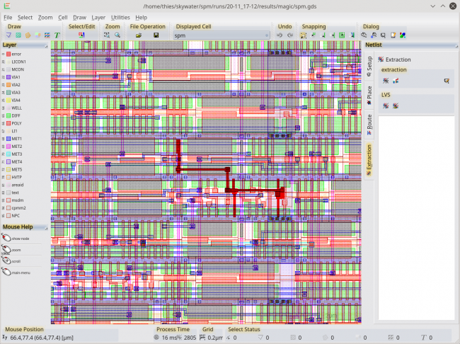
Nettracing
The autoLayerMacro.layout macro includes any setup required for a net tracing. To use it just load the design, open the netlist tools subwindow, goto the its extraction tab and call build connection and set node mode afterwards. Then any mouse click on a shape will highlight the complete net.
In the example shown below the a automatic generated RTL(verilog) to GDS flow of the openLane project is used. It show the example spm shiped with the project. OpenLane works fine with the SkyWater PDK.
RTL (verilog) to GDS
Extending the Place&Route flow described above a complete flow RTL to GDS can be performed. Just open the Verilog file inside the integrated TextEditor and call the macro RTL to GDS in the Utilities menu. The requirement on the system are identical as for the Place&Route flow. This flow is currently limited to a single Verilog file with the cell/module name identical to the file name. But extending it to multi file project can easily be done as the hole flow is Open Source using OpenROAD with Yosys. As the Place&Route flow see it as a template for your own adjustment including adjusting it for PDK for other Foundries.
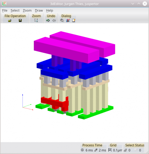
3D-View
To generate a 3d-view from the layout two steps are required. In the first step additional derived layers need to be created. This step is done by calling the macro mainmenu/Utilities/Texhnology/SkyWater/sky103a/crete derived layers. Afterward the 3d view can be created via the 3d-view sub windows with a extrude layer/cell or view feature. Once completed the additional layers can be removed by calling mainmenu/Utilities/Texhnology/SkyWater/sky103a/clear up created layers.
© 2026 juspertor GmbH