Class Reference cell
A single cell of a design with all features to modify it. More...
Member
Detailed Description
This class represents a single cell. Most important member of this class is firstElement . It is a linked list of all elements in this cell. It can be used to step through all elements. A typical macro to step through all element looks like:
       //get point to the current displayed cell
       cell *myCell=layout->drawing->currentCell;

       // pointer to the first element of the linked list of all element of the cell
       elementList *el= myCell->firstElement;

       // loop over all elements
       while (el!=NULL) {
           if (el->thisElement!=NULL) {
              if ( el->thisElement->isPath() ){
              // ...
              }
           }
         el=el->nextElement;
       }
With the other members of this class new shapes can be added and existing shapes can be selected and modified.
Member Function Documentation
element* cell::addBox(int x,int y,int w, int h,int layer)
A box is added to this cell. The box is defined by one of the corner points and the width and the height. For positive width and height the point will be the lower left corner of the box.
| Parameter: | |
|---|---|
| x | X value of the anchor point |
| y | Y value of the anchor point |
| w | width of the box |
| h | height of the box |
| layer | the number of the layer for the new box |
Returns: a pointer to the new box element is returned.
element* cell::addBox(pointArray points,int layer)
A box is added to this cell. The box is defined by an array of 5 points. The first and the last point have to be the same. If the box is rotated, a polygon is added instead of a box.
| Parameter: | |
|---|---|
| points | an array of 5 points. |
| layer | the layer number which will be used for the box. |
Returns: a pointer to the new box element is returned.
element* cell::addBox(rect r,int layer)
A box from a rectangle on layer is added to this cell.
| Parameter: | |
|---|---|
| layer | the number of the layer of the new box |
| rect | a rectangle object with values for all four sides of the box |
Returns: a pointer to the new element is returned.
element* cell::addCellrefArray(cell *c, pointArray array, int nx, int ny)
A cell-reference-array is added to this cell.
| Parameter: | |
|---|---|
| c | a pointer to the cell to be referred |
| array | A pointArray with three points defining the position of the array. The first coordinate is the array reference point (origin point). The second coordinate locates a position that is displaced from the reference point by the inter-column spacing times the number of columns. The third coordinate locates a position that is displaced from the reference point by the inter-row spacing times the number of rows. That means the spacing will be calculated like: space_x=(array.point(1)-array.point(0))/anzx; space_y=(array.point(2)-array.point(0))/anzy; |
| nx | number of entries in the X-axis |
| ny | number of entries in the Y-axis |
Returns: a pointer to the new element is returned.
element* cell::addCellrefArray(cell *c,point pos1,point pos2,int nx,int ny)
A cell-reference-array is added to this cell.
| Parameter: | |
|---|---|
| c | a pointer to the cell to be referred |
| pos1 | is the array reference point (origin point) |
| pos2 | will define x and y spacing. The x-value will be the x-spacing and the y-value will be the y-spacing. So only vertical and horizontal spacing is possible |
| nx | number of entries in the X-axis |
| ny | number of entries in the Y-axis |
Returns: a pointer to the new element is returned.
element* cell::addCellref(cell *c,point pos)
A cell-reference is added to this cell.
| Parameter: | |
|---|---|
| c | a pointer to the cell to be referred |
| pos | is the array reference point (origin point) |
Returns: a pointer to the new element is returned.
Example with adjusting the transformation after creation of the reference:
// finds the cell to place with the name 'noname'
cell *myCell=layout->drawing->findCell("noname"); // finds the cell to place

if (myCell==NULL) return 0; // cell not found, terminate script

point p;p.set(100,200); // define an origin point

element *e=layout->drawing->currentCell->addCellref(myCell,p); // creates the reference
strans trans; trans.rotate(180); // define a 180 deg rotation
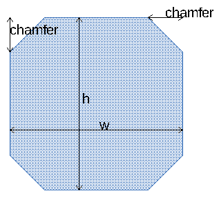
e->setTrans(trans); // set the transformation to the previous created referenceelement* cell::addChamferedBox(int x,int y,int w, int h,int chamfer, int layer)
Adds a chamfered box to the cell. x, y, w, h is identical to the addBox method. chamfer is the retraction in x or y for each corner. So the length of the chamfer will be sqrt(2) chamfer. The resulting shape is a polygon.
Returns: a pointer to the new polygon is returned.
See also: addBox(), addRoundedBox()
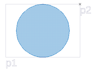
element* cell::addCircleBox(point p1, point p2,int layer)
A circle is added to this cell. p1 and p2 are the edges of the bounding box of the circle. If the dimension in one direction is smaller, the circle is place in the centre of the box with the lower diameter. The circle resolution is used from the setup.
Returns: a pointer to the new circle is returned.
element* cell::addCircle(int layer,point center,int radius, int numPoints=0)
A circle is added to this cell. The default circle resolution fron the setup is used, if numPoints is equal 0.
Returns: a pointer to the new circle is returned.
   // add a circle with the center at position (300,500) and 32 vertexes
element *e=layout->drawing->currentCell->addCircle(10,point(300,500), 700,32);element* cell::addCircle(int layer,point center,point circlePoint, int numPoints=0)
Adds a circle to the cell. The circle is defined by its center and a point an the radius. The default circle resolution from the setup is used, if numPoints is equal 0.
Returns: a pointer to the new circle is returned.
void cell::addCornerAreaSelect(double value1,double value2,int angleInt)
All corners of selected elements will be modified. A addition area will be added/substracted in the corner region. The amount of the area will be calculation in dependence with the corner angles. sharp corner will add more area than small angles. The first parameter will give the square of amount for a 90° angle. The second parameter will modify the shape of the added area. angleInt will limit the modification on some angles (positive/negative, sharp angle). 0 will modify all angles.
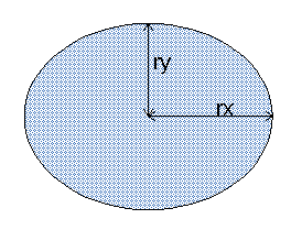
element* cell::addEllipse(int layer,point center,int rx,int ry)
A ellipse is added to this cell. The resulting shape is polygon with an elliptic shape. The circular-defaults from the setup are used to define the resolution.
| Parameter: | |
|---|---|
| center | the coordinates of the center |
| layer | the number of the layer of the new ellipse |
| rx | radius on the x-axis |
| ry | radius on the y-axis |
Returns: a pointer to the new element is returned.
See also: addCircle()
element* cell::addPath(pointArray points,int layer)
A path is added to this cell. The default path width from the setup is used. A pointer to the new created element is returned.
element* cell::addPath(pointArray points,int layer,int width)
A path with a defined width is added to this cell. A pointer to the new created element is returned.
element* cell::addPolygon(pointArray points,int layer)
A polygon is added to this cell.
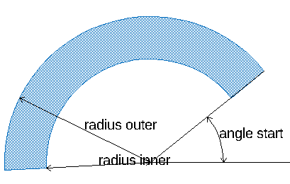
element* cell::addPolygonArc(point center, int radiusInner, int radiusOuter, double angleStart, double angleStop,int layer)
Adds a polygon arc to the cell. The resulting shape is a polygon.
| Parameter: | ||
|---|---|---|
| center | the center point | |
| radiusInner | smaller radius of the arc | |
| radiusOuter | smaller radius of the arc | arcsector starts |
| angleStop | counter clock wise angle to the x-axis where the arc ends | |
| layer | the layer number which will be used for the box. |
Returns: a pointer to the new element is returned.
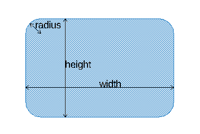
element* cell::addRoundedBox(int x,int y,int width, int height,int radius, int layer)
A rectangular polygon with rounded corners is added to this cell. The polygon is defined by one of the corner points and the width and the height. For positive width and height the point will be the lower left corner of the box. For the resolution of the circle corners the circular defaults from the setup are used.
| Parameter: | |
|---|---|
| x | X value of the anchor point. |
| y | Y value of the anchor point. |
| height | height of the box. |
| width | width of the box. |
| radius | radius of the corners |
| layer | the layer number which will be used for the box. |
Returns: a pointer to the new element is returned.
See also: addBox(), addChamferedBox()
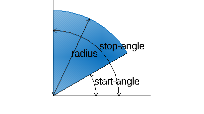
element* cell::addSector(point center, int radius, double angleStart, double angleStop,int layer)
Adds a sector to the cell. The resulting shape is a polygon.
| Parameter: | |
|---|---|
| x | X value of the center point. |
| y | Y value of the center point. |
| radius | radius of the sector |
| angleStart | counter clock wise angle to the x-axis where the sector starts |
| angleStop | counter clock wise angle to the x-axis where the sector ends |
| layer | the layer number which will be used for the box. |
Returns: a pointer to the new element is returned.
element* cell::addText(int layer,point pos, string text)
A text is added to this cell.
double cell::areaLayer(int layer)
Returns: area of all shapes on layer including overlaps and area on layer in referred cells. The unit of the result is in databseunits. So to get the area in square meters you need to multiply it with databseunits by the power of 2.
Example:
double areaLayer=layout->drawing->currentCell->areaLayer(1);
double area_in_square_meter=areaLayer*layout->drawing->databaseunits*layout->drawing->databaseunits;
double cell::areaSelect()
The area of all selected elements is calculated. The unit of the result is in databseunits.
double cell::areaSelected()
The area of all elements is calculated. The unit of the result is in databseunits.
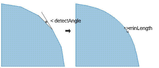
void cell::bowImprovementSelect( double detectAngle, double pointFactor,int minLength)
In selected path and polygon elements bow sections will be detected and improved. The bow detection is controled via the detectAngle parameter. Corners with an smaller angles will be assumed to be and bow. The bow itself will be recreated with a higher amount of vertexes. (introduced with release 20220419)
void cell::boxDeselect()
All boxes are deselected including boxes on layer that are currently invisible.
void cell::boxSelectVisible()
All visible boxes are selected. The selection status of boxes on invisible layer are unchanged.
void cell::cDeselect(rect select)
Deselects a cell, if the base point is in the rect.
string cell::cellName
The name of this cell.
void cell::chamferSelect(double value,int type,int angleInt)
Corners in selected shapes will get a chamfer. type specifies the how the value is defined. angleInt will limit the modification on some angles (positive/negative, sharp angle). 0 will modify all angles.
double cell::circumferenceSelect()
The circumference of all selected elements is calculated.
double cell::circumferenceSelected()
The circumference of all elements is calculated.
void cell::clearMirrorxSelect()
In selected text elements and cell references the mirror flag is cleared.(introduced with release 20220808)
void cell::clearProperties()
All properties in this cell are removed.
Several file format allows to store additional information to any shape called properties or attributes. Calling this method will delect this infomation of any element in the cell.
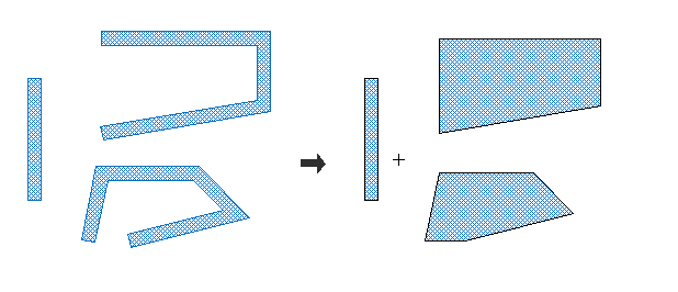
void cell::closeToPolygon()
Closes path elements to a polygon by adding a path segment. The width of the existing path is ignogred in this operation. The path need to have at least two segment to work. This method will only modify pathes.
See also: convertToPolygonIfClosed(), [cell:toPolygon()]
void cell::closeToPolygonSelect()
Identical to closeToPolygon() but only selected pathes will be converted.
void cell::compare(cell* Cell)
Tests, if this cell is the same as Cell. Non identical elements will be selected in both cells. All other elements will be deselected.
void cell::convertToPolygonIfClosed()
Converts all path elements to polygons, if the first point is identical with the last point..
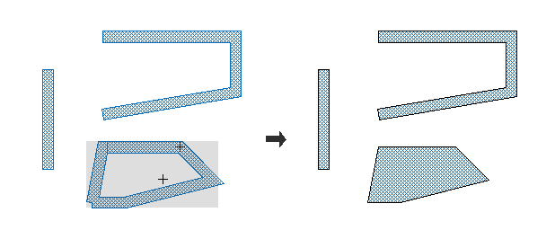
See also: closeToPolygon(), [cell:toPolygon()]
void cell::convertToPolygonIfClosedSelect()
Converts selected path elements to a polygon, if the first point is identical with the last point. So the operation is identical to convertToPolygonIfClosed() but will only effect selected pathes.
void cell::copyCell(cell* otherCell)
A flat copy of the otherCell will be added. Shapes are a full copy and changing any of the shapes will not effect otherCell. (introduced with release 20190808)
void cell::copySelect(point p)
Selected elements are copyed and move by p
| Parameter: | |
|---|---|
| p | movement |
int cell::countSelectCellref()
Returns: number of selected cellrefs
int cell::countSelectCellrefarray()
Returns: number of selected cellrefarrays
int cell::countSelectBox()
Returns: number of selected boxes
int cell::countSelectPath()
Returns: number of selected paths
int cell::countSelectAllPoints()
Returns: number of selected points in all selected shapes (path, polygon,box and text) (introduced with release 20240401)
int cell::countSelectPoints()
Returns: number of selected points in not completely selected shapes
int cell::countSelectPolygon()
Returns: number of selected polygons
int cell::countSelectText()
Returns: number of selected text
int cell::countSelectCircles()
Returns: the number of selected polygons that have a circular shape. Please note that these shape will also be counted with countSelectPolygon() (introduced with release 20220504)
int cell::countSelectElements()
Returns: the sum of countSelectText()+countSelectPolygon()+countSelectPath()+countSelectBox()+countSelectCellrefarray()+countSelectCellref() partly selected elements are not considered. (introduced with release 20220504)
int cell::countSelectShapes()
Returns: the sum of countSelectPolygon()+countSelectPath()+countSelectBox(), partly selected elements are not considered. (introduced with release 20220504)
void cell::cropSharpAnglesSelect(int i)
Angles smaler than 90° are removed by inserting additional points
void cell::cropWithSelection()
Selected elements are used to crop the complete cell.
void cell::cSelect(rect select)
Selects a cell, if the base point is in the rect.
void cell::cutSelect(point p1, point p2)
Cut selected elements between p1 and p2. So in the example blow the cut operation on a single polygon will result into three different polygons after the operatin.

void cell::deleteElement(element *e)
Delete the element e.
void cell::deleteLayer(int layer)
All shapes on layer in this cell will be deleted.
void cell::deleteRefs(cell *c)
Cellrefs and cellrefarrays on the cell c are deleted.
| Parameter: | |
|---|---|
| *c | pointer to the cell that will be removed |
void cell::deleteSelect()
All elements selected previously will be removed. In partial selected shapes the selected vertixes will be removed. Sp for example in case a single vertex from a polygon is selected this vertex will be removed from the polygon.
bool cell::depend(cell *Cell)
Returns: true if this cell or its cellrefs has a cellref to cell.
void cell::deselectAll()
All elements are deselected.
void cell::deselectCellref(string cellname)
All cell refercences or array of cell references to cells named cellname are deselected (introduced with release 20220726)
void cell::deselectLabeledShapesOnLayer(int layerText,string label, int layerShape=-1)
All shapes (polygons, pathes, boxes) on layerShape having a touching element with the text label on layerText are deselected. If label is an empty string all labeled shapes on layerShape are deselected. If layerShape is not given, shapes on layerText are deselected.
void cell::deselectLayer(int layer)
All elements on layer are deselected.
void cell::deselectNodeOnLayer(int node,int layer)
All elements on layer connected with node are deselected
void cell::deselectNode(int node)
All elements connected with node are deselected.
void cell::deselectShapeWithArea(double min,double max)
All shapes with an surface area between min and max are deselected.
void cell::deselectText(string text,int layer=-1)
All text elements with text are deselected. If the optional parameter layer is used, only text on that layer will be deselected.
void cell::detachHolesSelect(int outlineLayer, int holeLayer)
Selected polygons will be decomposed. The outline will be copied on the outlineLayer. Holes will be copied on the holeLayer. The original shapes will be deselected. If outlineLayer or holeLayer is negative, the corresponding shape will not be created.
void cell::edgeRemoveSelect(int i)
Edges smaller than i are removed.
void cell::fAllDeselect(rect select)
Deselects a complete element, if all points are inside rect.
void cell::fAllSelect(rect select)
Selects a complete element, if all points are inside rect.
void cell::fDeselectLayer(rect select, int layer)
Deselects a complete element, if one point is inside rect and it is on layer
void cell::fDeselect(rect select)
Deselects a complete element, if one point is inside rect.
void cell::filletRoundSelect(double value,int type,int angleInt)
Corners in selected shapes will be rounded. type specifies the how the value is defined. angleInt will limit the modification on some angles (positive/negative, sharp angle). 0 will modify all angles.
void cell::filletRoundBezier(double value,int type,int angleInt)
Corners in selected shapes will get a bezier shape. type specifies the how the value is defined. angleInt will limit the modification on some angles (positive/negative, sharp angle). 0 will modify all angles.
elementList* cell::firstElement
This is a list of all elements in this cell.
void cell::flatAllSelect()
Selected cellrefs and cellrefarrays are flatten. If the the cellrefs contain more cellrefs, they are flatten as well.
void cell::flatCellref(element *e)
The hierarchie of the given element is removed by one level and added to the cell. If the element is part of the cell it is removed. So it is a one level flat feature for the passed element. This function has no effect for shapes like polygons or paths. (introduced with version 20190807)
example:
cell *c=layout->drawing->findCell("find_Cell"); // search pointer to cell with name "find_Cell"
for (elementList*el=layout->drawing->currentCell->firstElement;el!=NULL;el=el->nextElement){
       if (el->thisElement->depend()==c){ // searches references to the search cell
              layout->drawing->currentCell->flatCellref(el->thisElement); // flat found references
       }
}
void cell::flatCellrefArray()
All cellrefarrays are flatten to simple cell references. This feature is usefull to prepare a design for a format that does not support arrays.
void cell::flatLayer(int layer)
All element on layer are flatten from the first hierarchie leel. They are not removed in the cell reference and double exists afterwards (in the cell and in the cell reference).
void cell::flatAllLayer(int layer)
All element on layer are flatten in all hierarchie levels. They are not removed in the cell reference and double exists afterwards (in the cell and in all cell references).
void cell::flatSelect()
Selected cellrefs and cellrefarrays are flatten.
void cell::fSelectLayer(rect select, int layer)
Selects a complete element, if one point is inside rect and it is on layer
void cell::fSelect(rect select)
Selects a complete element, if one point is inside rect.
void cell::fractureBoxSelect(int maxSize)
splits selected shapes into retangular boxes with a maximal size of maxSize. Boxes can overlap and may be non orthogonal to the axis.

void cell::fractureLineSelect(int lineWidth, int overlap=0, bool keepSmallShapes=false)
splits selected shapes into lines with a exact size of lineWidth. Lines can overlap and may be non orthogonal to the axis. The optional overlap parameter defines a minimum overlap of the lines. if the optional keepSmallShapes parameter is true, no shapes will be deleted in the case it is smaller than the lines width. Instead these shapes will be scale so that it can be fractured.

void cell::fractureNumberPointsSelect(int count)
Selected polygon will be cut horrizontal and vertical until the number of vertexes is less than the given value. (introduced with release 20240329)
void cell::fractureTrapezoidSelect(int maxSize)
splits selected shapes into trapezoid with a maximal hight of maxSize.

void cell::fractureTriangleSelect(int maxSize)
splits selected shapes into triangles with a maximal edge length of maxSize. In contrast to triangulateSelect() the original shape is replaced and the maximal edge length can be determine.

double cell::getDensityLayer(int layer,bool merge)
Returns: the density of the given layer. 1 mean that all shapes on the layer have together the same area than the bounding box of the cell. If merge is true, overlapping area will only be counted once.
doubleList cell::getDensityLayer(int layer, point pos, int sizeX, int sizeY, int stepX, int stepY, int nx, int ny)
The layer density is calculted. The density in squares of the size sizeXxsizeY is calculated. For a complete fill square 1 is returned. Overlapping area is calculated double.
int nx=4,ny=4, spaceX=1000, spaceY=1000, sizeX=500,sizeY=500;
doubleList a=layout->drawing->currentCell->getDensityLayer(1,p,sizeX,sizeY,spaceX,spaceY,nx,ny);
debug->clear();
int x,y;
for (x=0; x < nx;x++){
  for (y=0; y < ny;y++){
      debug(a.at(x*ny+y));
      }
    }
debug->show();
int cell::groupStructure(cell *cell_)
Searchs structures identical to cell_ and replace it with a cellref to this cell. The number of replaced structures is returned.
void cell::group(cell *cell_)
Selected elements are moved to cell_
bool cell::identical(cell *Cell)
Returns: true if this cell is identical to Cell; Non identical elements will be selected.
void cell::incircleSelect(int layer)
adds a circle inside any selected shapes with the maximum possible radius without intersection any edge of the selected shape. As the result the centre of circle is located at the pole of inaccessibility. The circles are added to layer.
void cell::invertSelect()
The selection of this cell is inverted.
void cell::mapLayer(layertranslator *t)
all elements in this cell are maped with layerTranslator t.
void cell::maximum(point *pos)
The maximum coordinates is returned, if bigger than pos. pos will keep unchanged, if the design does not contain any element.
void cell::maximumSelect(point *pos)
The maximum coordinates of all selected elements is returned, if less than pos. pos will keep unchanged, if no element is selected.
point cell::maximum()
The maximum coordinates is returned. The maximum possible coordinate is returned, if the design does not contain any element.
point cell::maximumSelect()
The maximum coordinates of all selected elements is returned. The maximum possible coordinate is returned, if the design does not contain any selected element.
rect cell::measureSpaceVisible(point p)
Returns: a rectange with the nearest shape edge any any direction of the given point p. If no edge in that direction exist, the bounding box coordinate for that direction is returned. (introduced with release 20181229)
Example: You design only contains a single box with left edge at x=10, right edge at x=50, top edge at y=-30, and bottom edge at y=-50
rect r=myCell->measureSpaceVisible(point(20,-40)); // will return left 10, right 50, top -30 and bottom -50
rect r=myCell->measureSpaceVisible(point(28,-32)); // will return left 10, right 50, top -30 and bottom -50
rect r=myCell->measureSpaceVisible(point(0,-40)); // will return left 10, right 10, top -30 and bottom -50, in y bounding box is return as no shape in y direction, y the left edge is returned
rect r=myCell->measureSpaceVisible(point(20,0)); // will return left 10, right 50, top -30 and bottom -30, bounding box for measurement in x and upper bouning box for measurement in y
void cell::mergeSelect()
Selected elements on the same layer are merged.
void cell::minimum(point *pos)
The minimum coordinates is returned, if less than pos. pos will keep unchanged, if the design does not contain any element.
void cell::minimumSelect(point *pos)
The minimum coordinates of all selected elements is returned, if bigger than pos. pos will keep unchanged, if no element is selected.
point cell::minimum()
The minimum coordinates is returned. The minimum possible coordinate is returned, if the design does not contain any element.
point cell::minimumSelect()
The minimum coordinates of all selected elements is returned. The minimum possible coordinate is returned, if the design does not contain any selected element.
void cell::minkowskiSumSelect(pointArray polygon)
With all selected polygons the Minkowki Sum with polygon will be calulated. Original shapes will be replaced by the sum shapes on the same layer. All shapes will be converted to a polygon by this operation.
pointArray pa;
pa.attach(200,200);
pa.attach(100,100);
pa.attach(100,0);
pa.attach(200,200);
layout->drawing->currentCell->minkowskiSumSelect(pa);
void cell::mirrorSelect(point p1,point p2)
Selected elements are mirror at a Line made by p1 and p2. If p1==p2, it is mirrored at this single point.
void cell::move(point pos)
All element are moved by pos
void cell::moveSelect(point pos)
Selected element are moved by pos
void cell::moveToLayerSelect(int layer)
Selected elements are moved to the layer
Parameter:
layer new layer
elementList* cell::nearestElement(point p)
Returns: the nearest element to the point p.
void cell::pDeselect(rect select)
Deselects point in the rect.
void cell::pSelect(rect select)
Selects point in the rect.
void cell::pathDeselect()
All path elements are deselected.
void cell::pathSelectVisible()
All visible path elements are selected.
bool cell::pointOnLayer(point p,int layer)
Returns: true, if the point p is inside any shape of layer, otherwise false is returned. (introduced with release 20181229)
void cell::polygonDeselect()
All polygons are deselected.
void cell::polygonSelectVisible()
All visible polygons are selected.
void cell::punchWithSelection()
All shapes and part of shapes located inside of a selected shapes is remove from the cell. Referred cell are adjust if required.
void cell::relinkSelect(cell *Cellnew)
Selected cellref are relinked to Cellnew.
void cell::relink(cell *Cellold,cell *Cellnew)
Cellreferences to Cellold are relink to Cellnew.
int cell::replaceText(string text1,string text2)
If text element are named text1, it is replaced with text2.
Returns: number of replacements
void cell::resize(double scale)
Multiply all elements with the factor scale. As result this will be a scaling for any basic shape (path, box, polygon, text). On cell references and cell array references only origin point and the spaceing will be multiplied. The magnification will kept untouched. So calling resize on any cell of a design will be a complete scaling of the design. Calling it for a single cell will not. To scale a single cell please use the scale feautre
void cell::rotateSelect(double angle,point pos)
Selected elements are rotated.
| Parameter: | |
|---|---|
| angle | angle counterclock |
| pos | center of rotation |
void cell::roundSelect(int i)
Selected shapes/points are rounded to a multiply of i. Cell references and Cell arrays are never modified.
void cell::scaleSelect(point origin,double scale)
Selected elements are scaled. origin the the point which will no moved. scale is the scaling factor.
void cell::scaleSelect(point p1,point p2,point p3)
Selected elements are scaled. p2 is scale to p3.
| Parameter: | |
|---|---|
| p1 | orgin |
| p2 | old point |
| p3 | new point |
void cell::selectAll()
All elements are selected.
void cell::selectArea(double minArea, double maxArea, int layerSource)
selects shapes on layer sourceLayer having an area between minArea and maxArea. (introduced with release 20220415)
void cell::selectCellref(string cellname)
All cellref to cells named cellname are selected
void cell::selectDatatype(int i)
All element with the datatype i are selected.
void cell::selectDimension(int minWidth, int maxWidth, int minLength, int maxLength, int layerSource)
selects shapes on layer sourceLayer having an certain dimentsion. The length is always the longer side of the bounding box while width labels the shorter size of a bounding box. (introduced with release 20220415)
element* cell::selectedElement(element *e=NULL)
Returns: the first complete selected element after e. If e is NULL, the first selected element in the element list is returned. This method can be used to perform a loop over all selected shapes:
 cell *c=layout->drawing->currentCell;
 int count=0;
 element *e=NULL;
 do {
   e=c->selectedElement(e);
   if (e!=NULL) count++;
 } while (e!=NULL);
 debug(count);
 debug.show();
void cell::selectIdentical()
elements having a identical structure with already selected elements will be selected as well. For for example if you have a single box on layer A with the size 10µm 20µm selected. Any other box on layer A* having the same width of 10µm and height of 20µm will be selected as well. (introduced with release 20220505)
void cell::selectLabeledShapesOnLayer(int layerText,string label, int layerShape=-1)
All shapes (polygons, pathes, boxes) on layerShape having a touching element with the text label on the layerText are selected. If label is an empty string all labeled shapes on layer are selected. If layerShape is not given, shapes on layerText are selected.
void cell::selectLayer(int layer)
All elements on layer are selected.
void cell::selectNodeOnLayer(int node,int layer)
All elements on layer connected with node are selected
void cell::selectNode(int node)
All elements connected with node are selected.
void cell::selectRelation(int layerA, int layerB, string relation)
selects shapes on layer layerA having a certain relation to shapes on layer layerB. The supported releations are very similar to the derived layer feautre:
| Relation: | Result: |
|---|---|
| avoiding | The shapes on layerA that are completely outside and do not touch the shapes on layerB |
| butting | The shapes on layerA that abut the shapes on layerB; the shapes on layerA must have at least one coincident edge with the shapes on layerB and must otherwise be completely or partially outside the shapes on layerB |
| buttingOrCoincident | The shapes on layerA that have any coincident edges with the shapes on layerB; Shapes may abut, overlap, or be completely contained |
| buttingOrOverlapping | The shapes on layerA that touch, overlap, or are contained within the shapes on layerB; like “touching” except this may have parameters |
| buttOnly | The shapes on layerA that abut – but do not overlap – any shapes on layerB (i.e., have only a coincident edge in common) |
| coincident | The shapes on layerA that have any coincident edges with the shapes on layerB; Some part or all of the shape on layerA must overlap the corresponding shape on layerB; Shapes that abut only are excluded |
| coincidentOnly | The shapes on layerA that are completely contained within, and have at least one coincident edge with, the shapes on layerB |
| enclosing | The shapes on layerA that completely contain one or more shapes on layerB |
| inside | The shapes on layerA that are completely contained within the shapes on layerB (coincident edges are allowed) |
| outside | The shapes on layerA that are completely outside of the shapes on layerB; Shape edges may abut but not overlap |
| overlapping | The shapes on layerA that are completely or partially contained within the shapes on layerB; Shapes that abut but do not overlap are excluded |
| straddling | The shapes on layerA that overlap at least one edge of the shapes on layerB. At least one point of the layerA shape must be outside the corresponding shape on layerB. Shapes that abut but do not overlap are excluded. |
| touching | The shapes on layerA that abut, overlap or are contained within the shapes on layerB |
(introduced with release 20220415)
void cell::selectShapeWithArea(double min,double max)
All shapes with an surface area between min and max are selected.
void cell::selectText(string text, int layer=-1)
All text elements with text are selected. If the optional parameter layer is used, only text on that layer will be selected.
int cell::selectTouchingOrOverlapping(element *)
int cell::selectTouchingOrOverlapping(pointArray pa)
int cell::selectTouchingOrOverlapping(rect)
Any shape touching or overlapping the given element, pointArray or rect is selected. The number of selected shapes is returned.
void cell::selectVisible()
All visible elements are selected.
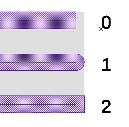
void cell::setCapSelect(int cap)
In selected path elements the caps is set to cap. (0 for no cap, 1 for round caps, 2 for square caps)
void cell::setDatatypeSelect(int i)
The datatype of selected element is set to i.
void cell::setMirrorxSelect()
In selected text elements and cell references the mirror flag is set.(introduced with release 20220808)
void cell::setPresentationSelect(int p)
In selected text elements the presentation is set to p. Possible values are identical to element::setPresentation(). (introduced with release 20220808)
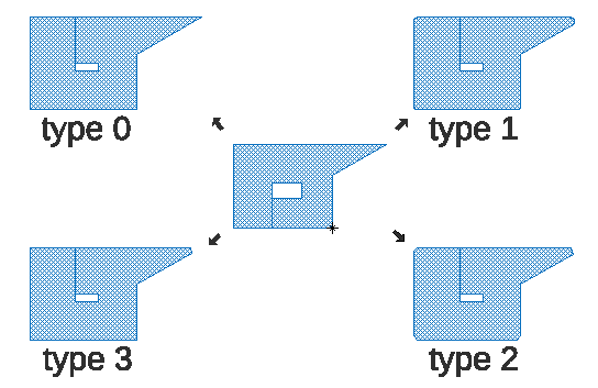
void cell::sizeAdjustSelect(int value,int type)
Selected elements grow/shrink with value. With type sizing style can be set.
| type | style |
|---|---|
| 0 | linear edge move |
| 1 | rounded corners |
| 2 | octagon sizing |
| 3 | like 0 with cutting sharp angles corners |
void cell::sizeAdjustSelect(int valueX, int valueY,int type)
Selected elements grow/shrink with value. With type sizing style can be set, in the moment only type 0 is supported.
void cell::slotSelect(int slotWidth, int minSlotLength, int maxSlotLength, int edgeSpacing, int minSlotspacing )
In selected shapes slots will be added. This is usually used the reduce film stress problems in wide metall layers.
See also: InsertSlots
void cell::snapShapeSelect(int i)
Selected elements/point will snap to near elements with a search radius of i.
void cell::snapPatheSelect(int i)
Endpoints of selected paths will snap toother selected endpoints in case both endsegments have the same orientation. The maximal possible movmane is limited to i in database units. This feature was introduced with release 20230730.
void cell::sortElements(string type)
The linked list with all elements will be sorted. A consequent editing operation may break the sorting again. Sorting has effect for output to several file formats like GDS. (introduced with release 20220512)
| type | style |
|---|---|
| xMin | shapes are sorted in ascending order by the minimal x value of the bounding box |
| xMax | shapes are sorted in ascending order by the maximal x value of the bounding box |
| xCenter | shapes are sorted in ascending order by the center x value of the bounding box |
| yMin | shapes are sorted in ascending order by the minimal y value of the bounding box |
| yMax | shapes are sorted in ascending order by the maximal y value of the bounding box |
| yCenter | shapes are sorted in ascending order by the center y value of the bounding box |
| sizeX | shapes are sorted in ascending order by the size in x direction |
| sizeY | shapes are sorted in ascending order by the size in y direction |
| size | shapes are sorted in ascending order by the size (maximum of x direction and y direction) |
void cell::stripIdenticalElements()
If a cell contains two identical elements at the same position, it is impossible to see it. This function will detect this and remove one of the element.
void cell::swapLayerSelect(int i,int k)
This function swap the layers i and k of the selected elements in the this cell.
void cell::swapLayer(int i,int k)
This function swap the layers i and k in the this cell.
void cell::textDeselect()
All text elements are deselected.
void cell::textSelectVisible()
All visible text elements are selected.
void cell::textToPolygon(int defaultWidth)
all text elements are converted to polygon. defaultWidth will be used for text element with a scale independent size. If defaultWidth is 0, scale independent text elements are unchanged. This function works on all text elements including non selected text elements.
void cell::toBox()
Converts element to a box element if possible.
void cell::toBoxSelect()
Converts selected element to a box element if possible.
void cell::toCircleSelect()
Converts selected element polygon and box element to a circle. The circle is fitted in all existing points of the element.
void cell::toggleMirrorxSelect()
In selected text elements and cell references the mirror flag is toggled.(introduced with release 20220808)
void cell::toLines()
Converts all path elements to a path for each segment of the path.
void cell::toLinesSelect()
Converts selected path elements to a path for each segment of the path.
void cell::toMeshSelect(int width,int spaceing)
Selected elements are converted to a mesh of path elements with the width and spacing.
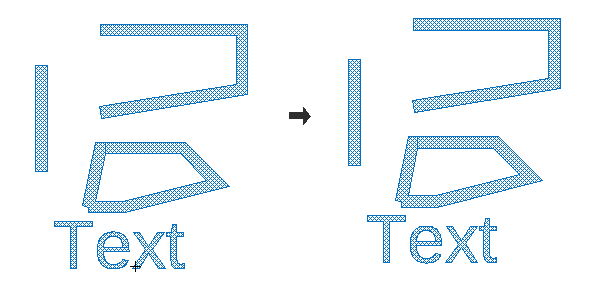
void cell::toPolygon()
Converts element to a polygon if possible. the resulting shape is not changed. So you will hardly notice the effect unless you invest the type of these shapes.
This operation will also convert text elements to polygon. For photomask production this usually means that the text element ignored for photomask exposure will now as poly be respected and the text element will get visible on a photomask.
void cell::toPolygonSelect()
Converts selected element to a polygon if possible. So it is identical to toPolygon() but will only effect selected shapes.
void cell::toPath()
Converts element to a pathes with its outline.

void cell::toPathSelect()
Converts selected element to a pathes with its outline. So the operation is identical to toPath() but will only effect selected shapes.
void cell::triangulateSelect(int layer)
Selected polygon are triangulated. The result is added to layer.

bool cell::useCell(cell *Cell)
Returns: true if this cell has a cell-reference to Cell. otherwise false is returned.
Obsolete Members
void cell::sizeadjustSelect(int value)
Selected elements grow/shrink with value.
OBSOLETE: Please use cell->sizeAdjustSelect(int value,int type=0) instead.
void cell::sizeadjustSelect(int valueX, int valueY)
Selected elements grow/shrink with different values in x and y.
OBSOLETE: Please use cell->sizeAdjustSelect(int valueX, int valueY, int type=0) instead.
void cell::modifyCornersSelect(double value1,double value2)
OBSOLETE: Please use addCornerAreaSelect instead!
All corners of selected elements will be modified. A addition area will be added/substracted in the corner region. The amount of the area will be calculation in dependence with the corner angles. sharp corner will add more area than small angles. The first parameter will give the squart of amount for a 90° angle. The second parameter will modify the shape of the added area.
© 2026 juspertor GmbH