Background Images
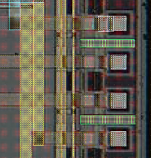
An image at the background of the design can be useful for many tasks. e.g. checking fabrication problems or for connecting nano-tubes, designing a device for an existing structured substrate. The LayoutEditor has the feature to load, place and vectorize images in the background of the design. Any pixel graphic format can be used. Unlimited images can be loaded concurrently. Also, live images can be used as background.
Display of Images in the Background
To start with background images, go to the misc menu within the utilities menu. The item, Set Background Image, will open a file dialog to choose an image. Afterward, a docking window will be displayed with all of the available image placement options.
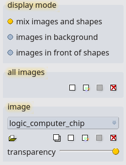
By default, the background image will only be displayed in one cell; this is the cell being shown when the image was opened. This default condition can be changed at any time within the docking window. An image can be made visible for all cells or it can even be made completely invisible.
Also, the display mode of the background images can be set. An image can be displayed in the background, in front of the design or mixed with the shapes. This setting is global for any display image. The transparency of the image can be set individually for each image. This is done with a slider inside the dock.
Alignment of Images
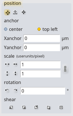
placing background There are three possible ways to place an image. The mouse can be used to move, scale or rotate an image while in the placing mode. A value can be entered via the dialog box, the Command Line, or by using the Auto Adjust Background.
Auto Adjust Background
The active background image will be moved in an automatic way after some alignment points are entered.
Set a series of images and design points with a left mouse click. The points had to enter alternating. First, an image point has to be entered followed by a design point. The automatic adjustment will be done in the way that the image point will be over the afterward entered design point. A shift left mouse click or control left mouse click will trigger the automatic alignment. The background image will be moved in a way that the image point is on the design point as close as possible.
Vectorization of Images to the Design
Loaded background images can be vectorized to a regular design. For vectorization, two different methods are available:
-
pixel: all pixels of a defined color range will be added to the active layer.
-
threshold: between a shape color range and a background color range a threshold will be calculated. The area within the threshold will be added to the active layer. By using this method a resolution higher than the pixel resolution of the background image can be obtained.
In both methods, the generated shapes will be added to the active layer in the current call. Also, an ignored area can be defined. Areas or holes smaller than the designated size will be ignored during vectorization.
Usage of the Pixel Method
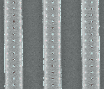
Place, scale and align the image to the position you need and go to the vectorization part of the Background dock:
![]()
- Choose the pixel method,
- Choose the shape color either by dialog or directly from the image,
- Choose a shape color range, the later vectorize part will be highlighted,
- Make the target layer active,
- Press Vectorize.
Usage of the Threshold Method
Place, scale and align the image to the position you need and go to the vectorization part of the Background dock:

- Choose the threshold method,
- Choose the shape color either by dialog or directly from the image,
- Choose a shape color range, the later vectorize part will be highlighted,
- Do the same with the background color (background color and shape color must not overlap, or vectorizing will fail in that case),
- Define a threshold,
- Make the target layer active,
- Press Vectorize.
© 2026 juspertor GmbH