Place & Route
Place
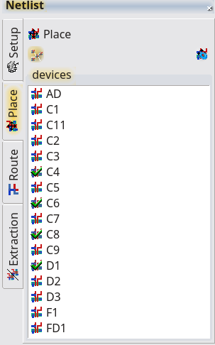
In the Place tab of the netlist tool, all devices of the current netlist are displayed. The icon in front of the device name shows the status of the device:
- grey icon: layout found
- colored icon: layout found and loaded, click will start place mode of the device
- green hook: device is placed, a click will highlight the device
In the place mode, the required connections are displayed. This display requires the connecting pins of the devices to be labeled on a connecting layer with its pin name. The Display Connection options have to be turned on.
Auto-Place
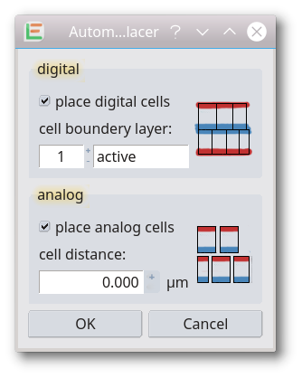 A simple automatic placement of the netlist devices. The current netlist will be check for already placed devices. Unplaced devices will be check for analog/digital device. Digital devices will be detected on the step and repeat box/bounding box. Digital devices will be placed by this box in rows with every second row mirrowed. Devices will be sorted with a little optimation in connecting length. Analog devices will be placed unsorted with a empty bounding area.
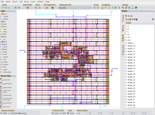
Route
The Route tab contains a list with any net. A click an on item will start the assist routing mode. The required connections are highlighted in the design. The routing dimentions are taken from the layer settings. With a double click on an item you can set the status of the net. The status will be automatically set after calling the LayoutVersusSchematic (LVS) tool.
Autoroute
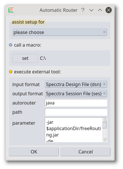
An external automatic routing tool will be called. The input/output format and the used tool can be choosen from a dialog. Current supported formats are Specctra Design File (dsn) and Specctra Session File (ses) as well as DEF files. The interface has been tested with FreeRouting and qrouter. These are both open source tools and included into the LayoutEditor package. FreeRouting indented for PCB design. The routing interface is very flexible and can be used with nearly any router. To change an existing setup, press the Auto-Router feature with the shift key pressed.
Auto Place&Route of Digital Blocks
For automatic Place&Route of digital circuit blocks, the OpenROAD toolkit with all the required tools is included in most packages. OpenROAD can be triggered by setting up a macro inside the Automatic Router setup or by calling a coresponding script from the menu. For some technologies an automatic place&route macro is included in the LayoutEditor package. These macros will trigger the core OpenROAD script. This script always needs to be adjusted to your requirements. For help with OpenROAD, please see its homepage.
© 2026 juspertor GmbH