Global Tools
Global Tools is an aggregation of several features. These features are not limited to modifying only currently visible cells, they can modify the whole design. For some of the features in the menu, there are identical features in other menus with a limitation to the selected shapes. All features Global Tools are not limited to the current cells and are not limited to selected shapes. All here listed tools are located under Utilities > Global Tools
Copy Layer
The Copy Layer function within the Global Tools menu is used to duplicate all geometric elements from one layer to another across the entire design. Key aspects of this tool include:
- Global Scope: Unlike standard copy-paste operations, this tool is not limited to the currently visible cell. it processes all shapes on the specified layer throughout every cell in the design hierarchy.
- No Selection Required: The function ignores whether shapes are currently selected. It automatically includes every shape present on the source layer.
- Layer-to-Layer Transfer: All shapes from the source layer are replicated onto the target layer, while the original shapes remain unchanged on the source layer.
- Hierarchy Preservation: The tool maintains the structural integrity of the design by performing the copy operation within each individual cell where the source layer is used. This ensures that the design hierarchy remains intact and consistent.
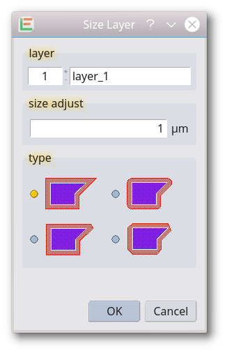
Size Layer
Shapes on the entered layer are changed in all cells of the design. Positive sizing values will grow the shapes, negative values will shrink shapes. If the design contains scale references, resulting shapes in these references may appear to be scaled differently. Use the feature Remove Scaled References to avoid it. Different types of sizing can be set. To size only selected shape please use the feature Size Adjust in the Adjust Utilities menu.
Delete Layer
The Delete Layer function within the Global Tools menu is used to permanently remove all geometric elements from a specific layer throughout the entire design hierarchy. Key characteristics include:
- Global Scope: This tool processes every cell in the design. It is not limited to the currently visible cell or the top-level cell.
- No Selection Required: The function automatically identifies and removes all shapes on the designated layer regardless of whether they are selected or not.
- Specific Layer Targeting: Only shapes on the chosen layer are deleted. All other layers remain completely unaffected.
Extract Layer
All elements on layers other than the selected one are removed. The function is used in the preparation for mask manufacturing. Please note: The design name is not modified so be careful not to overwrite your original design.
Separate Layer
A chosen layer is moved to a new design window and removed from the current design. A new layout window will be opened when executing the feature. Please note: Be careful when saving the original design if it was modified.
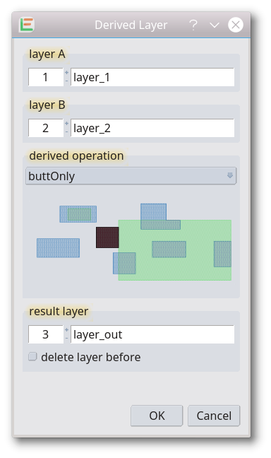
Derived Layer
A derived layer will be created from one or two existing layers. Different derivation operations are available. To create a derivation using a Boolean Operation, please use the BoolOnLayer feature of the Boolean tools. This feature was introduced with release 201801004.
These derivation operations are available:
| Operation: | Result: | |
|---|---|---|
| avoiding |  |
The shapes on layer A that are completely outside and do not touch the shapes on layer B |
| butting |  |
The shapes on layer A that abut the shapes on layer B. The shapes on layer A must have at least one coinciding edge with the shapes on layer B and must otherwise be completely or partially outside the shapes on layer B |
| buttingOrCoincident | 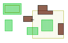 |
The shapes on layer A that have any coinciding edges with the shapes on layer B. Shapes may abut, overlap, or be completely contained |
| buttingOrOverlapping |  |
The shapes on layer A that touch, overlap, or are contained within the shapes on layer B. for example the shapes could be “touching”, be aware that this may have parameters |
| buttOnly | 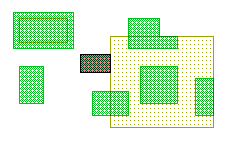 |
The shapes on layer A that abut – but do not overlap – any shapes on layer B, for example they only have a coincident edge in common |
| coincident | 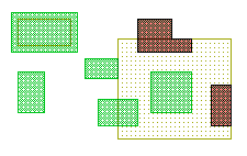 |
The shapes on layer A that have any coinciding edges with the shapes on layer B. Some part or all of the shape on layer A must overlap with the corresponding shape on layer B. Shapes that only abut are excluded |
| coincidentOnly |  |
The shapes on layer A that are completely contained within, and have at least one coincident edge with, the shapes on layer B |
| enclosing | 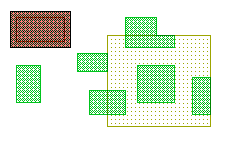 |
The shapes on layer A that completely contain one or more shapes on layer B |
| inside | 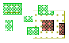 |
The shapes on layer A that are completely contained within the shapes on layer B, coincident edges are allowed |
| outside | 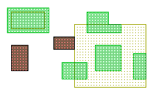 |
The shapes on layer A that are completely outside of the shapes on layer B. Shape edges may abut but not overlap |
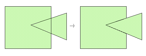
| overlapping | 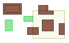 |
The shapes on layer A that are completely or partially contained within the shapes on layer B. Shapes that abut but do not overlap are excluded |
| straddling | 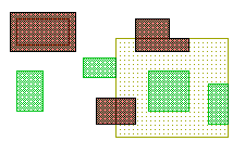 |
The shapes on layer A that overlap at least one edge of the shapes on layer B. At least one point of the layer A shape must be outside the corresponding shape on layer B. Shapes that abut but do not overlap are excluded. |
| touching | 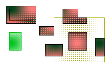 |
The shapes on layer A that abut, overlap or are contained within the shapes on layer B |
| grow | 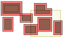 |
The shapes on layer A extended at each side with a fixed value |
| shrink | 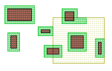 |
The shapes on layer A downsized at each side with a fixed value |
| growVertical | 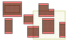 |
The shapes on layer A extended at vertical sides with a fixed value, diagonal edges are sized proportionally. |
| growHorizontal | 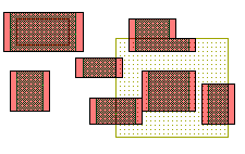 |
The shapes on layer A extended at horizontal sides with a fixed value, diagonal edges are sized proportionally. |
| shrinkVertical | 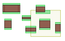 |
The shapes on layer A downsized at vertical sides with a fixed value, diagonal edges are sized proportionally. |
| shrinkHorizontal | 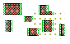 |
The shapes on layer A downsized at horizontal sides with a fixed value, diagonal edges are sized proportionally. |
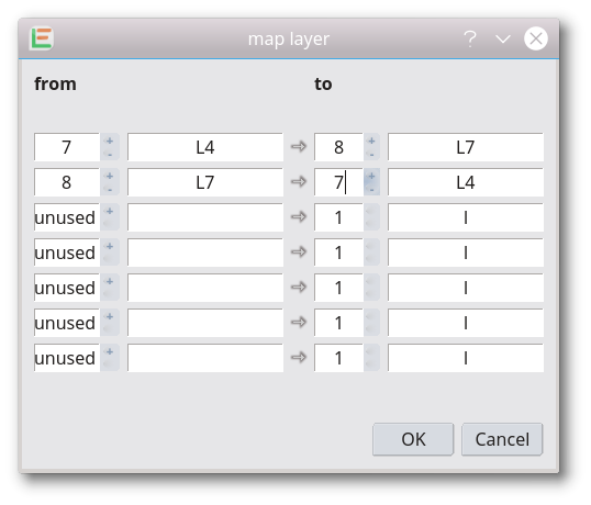
Map Layer
With this feature, layers can be changed in the whole design including merging different layers on a single one or swapping two layers.
Remove Overlap
The Remove Overlap function is a hierarchical tool designed to eliminate redundant geometries within a design. So overlapping shapes on the selected layer will be modified in a way that the overlap is removed without changing the resulting shape. Key characteristics of this function include:
- Single Layer Modification: The operation is performed strictly on the chosen layer. It ignores which shapes are selected and processes all shapes on that specific layer throughout the entire design. No other layers are affected.
- Hierarchy Preservation: Unlike standard Boolean tools, which often flatten the design or merge shapes into the top cell, 'Remove Overlap' is hierarchy-aware. It maintains the existing cell structure as much as possible.
- Minimal Intervention: To perform the overlap removal, the cell hierarchy is only modified where absolutely necessary. If required to resolve an overlap between different cell references, the function intelligently manages the instances (e.g., by creating cell variants) to ensure the resulting layout is clean while keeping the overall design structure intact.
Remove Cell Arrays
The Remove Cell Arrays function is a global utility used to expand all arrayed cell references into individual cell instances. Key features include:
- Expansion of Arrays: Every cell array reference (e.g., a 10 times 10 grid of a specific sub-cell) is replaced by the corresponding number of individual, independent cell references.
- Global Scope: This operation is applied to every cell within the entire design, not just the currently active or visible cell.
- Design Result: After running this tool, the resulting design will contain no more arrayed references, while the physical appearance and layout of the design remain identical.
- Format Compatibility: This feature is particularly useful when exporting to file formats that do not support internal array structures (e.g., some older CAD formats or specialized manufacturing tools) or when individual instances need to be manipulated separately.
Remove Non-Orthogonal Cell References
The Remove Non-Orthogonal Cell References function is a hierarchical utility used to ensure that all cell instances in a design are placed at orthogonal angles (0, 90, 180, or 270 degrees). Key characteristics include:
- Global Scope: This tool processes every cell in the entire design hierarchy, not just the active cell.
- Orthogonalization: Any cell reference placed at a non-orthogonal angle (e.g., 45 degrees) is replaced. The tool typically creates a new version of the cell where the internal geometry is rotated, allowing the instance reference to be updated to an orthogonal placement while preserving the physical layout.
- Array Handling: This specific feature does not modify cell array references; it only affects individual cell instances.
- Compatibility: This function is essential when preparing layouts for manufacturing equipment or software tools that only support Manhattan (orthogonal) rotations and cannot handle arbitrary angle placements.
- Visual Consistency: The physical appearance of the design remains unchanged; only the underlying hierarchical structure and rotation properties are adjusted to meet orthogonal requirements.
Remove Rotated Cell Arrays
The Remove Rotated Cell Arrays function is a hierarchical utility designed to handle cell arrays that have a rotation applied and replaces them with individual instances. Key features include:
- Global Scope: The tool scans the entire design hierarchy across all cells, identifying any array references that are placed with a rotation.
- Array Expansion: It replaces rotated cell arrays with individual cell references (instances). Since many standard file formats and manufacturing tools have limitations on how rotated grids are defined, expanding them into single instances ensures the layout is interpreted correctly. even some GDSII tools interpret rotated references differently. So it is recomended to avoid rotated array references in general.
- Physical Integrity: The visual and physical arrangement of the cells remains identical. The only change is how the data is structured internally—from a single rotated "array" object to multiple individual "reference" objects.
Remove Scaled References
The Remove Scaled References function is a hierarchical utility used to eliminate magnification factors from cell instances within a design. Key features include:
- Global Scope: This tool processes the entire design hierarchy, scanning all cells for any instances that have been placed with a scale factor other than 1.0.
- Normalization of Instances: It replaces scaled cell references with unscaled ones. To maintain the correct physical layout, the tool typically creates a new cell variant where the geometry itself is scaled, allowing the instance to be placed at a scale of 1.0.
- Array Handling: This specific feature does not modify cell array references; it only affects individual cell instances.
- Compatibility: This is highly useful when preparing designs for tools, masks, or file formats (like CIF) that do not support scaled cell references or handle them inconsistently.
- Physical Integrity: The visual and physical representation of the design remains identical; only the underlying hierarchical structure is adjusted to remove the scaling property from the references.
Delete Text
The Delete Text function within the Global Tools menu is used to permanently remove all text elements from the entire design. Key characteristics include:
- Global Scope: This operation is performed across all cells in the design, not just the currently active or visible cell.
- No Selection Required: The tool automatically identifies and deletes every text element regardless of whether it is selected or not.
- Targeted Removal: Only text elements are affected. All other geometric shapes like polygons, paths, and boxes remain untouched.
- Hierarchical Cleanup: The function processes the entire design hierarchy, ensuring that text is cleared from every sub-cell, which is often useful for preparing designs for manufacturing processes where text labels might not be supported or desired.
Delete Zero Width Path
The Delete Zero Width Path function is a global cleanup utility used to remove path elements that have no physical thickness. Key aspects of this tool include:
- Global Scope: The operation is performed across the entire design hierarchy. Every cell in the design is scanned and processed.
- Targeted Removal: It specifically identifies and deletes paths with a width of 0 or less. These elements are often unintentional or used as temporary construction lines that should not be part of the final physical layout.
- No Selection Required: You do not need to select the paths manually; the tool automatically finds and removes all matching elements throughout the design.
- Design Integrity: Only zero-width paths are removed. Paths with a valid width, as well as all other shapes like polygons, boxes, and text, remain untouched.
© 2026 juspertor GmbH