Process
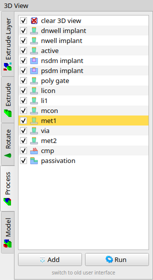
The Process tab in the 3d dock runs an ordered list of fabrication-like steps (extrude, etch, doping, deposit, fill, planarize, …) from the current 2d cell into the 3d view. The list is a JSON recipe. This tab is available from release 20260825.
It replaces the older Deposit tab as the default. A link at the bottom of the tab switches back to that interface.
Using the tab
Each row is one step. The checkbox enables or skips it. Double-click a row (or context menu Edit) to open the step dialog. Add appends a step; Run executes all enabled steps into the current 3d cell (one undo slot).
The context menu also offers move up/down, add above/below, Run until here, delete, and Load recipe… / Save recipe….
A PDK can ship 3d_process.json next to loadLayers.layout ($PDK/libs.tech/LayoutEditor/). Open-PDK import copies that file for technologies that include it. The Technology menu item 3D process loads it and builds the 3d view.
From a script:
layout->view3dTool->loadProcessRecipe("/path/to/recipe.json");
layout->view3dTool->runProcess();
The current list is stored in the setup (setup/3d/processRecipe) and restored on the next start.
JSON recipe
The file is UTF-8 JSON. Lengths, coordinates, and z values are database units of the 2d layout (the same integers as in the layout window). Angles are degrees. The runner accepts either an object with a steps array or a bare array of steps:
{
 "steps": [ { "op": "extrude", "layer": 1, "source": 1, "z0": 0, "z1": 1000 } ]
}
Any other key on the root object is ignored (name, units, comments, …). Unknown keys on a step are ignored as well.
Run does not clear the 3d cell first. Put a clearView step at the start if the recipe should replace the previous result.
If a step fails, the remaining steps are not run. The message is prefixed with the step name when that field is set.
Common fields
| Key | Type | Meaning |
|---|---|---|
op |
string | Step type. Required. |
name |
string | Label in the list. If omitted, a default such as extrude MET1 is used. |
enabled |
bool | If false, the step is skipped. Omit or true to run. Matches the checkbox. |
optional |
bool | If true and the 2d mask is empty (or doping produces no volume), skip the step instead of failing. |
layer |
int | Destination LayoutEditor layer index (layer manager number). Colour and, when z/thickness are omitted, the 3d level/thickness of this layer. Not used for planarize, setSurface, resetSurface, clearView. |
2d mask
Used by extrude, etch, dope, deposit, fill, setSurface. The first matching form wins:
rect— axis-aligned box[x0, y0, x1, y1]in DBU.polygons— array of rings. Each ring is a flat list[x0, y0, x1, y1, …](at least three points). The ring is closed if needed. Paths and boxes selected in the editor are stored in this form.source— layer or selection (see below).- If
sourceis omitted,layeris used as the mask layer.
| Key | Type | Meaning |
|---|---|---|
source |
int | ≥ 0: shapes on that LayoutEditor layer. -2: current selection (if none, all shapes of the cell). -3: all shapes of the cell. |
datatype |
int | With source ≥ 0, keep only shapes with this GDS datatype. Omit to use every datatype on the layer. |
invert |
bool | Invert the mask against the cell bounding box (or invertUniverse). |
invertUniverse |
array | Optional invert bounds [x0, y0, x1, y1] in DBU. |
Several polygons on the same layer are unioned for extrude.
Operations (op)
Aliases: doping → dope, clear → clearView.
extrude
Prism (or loft) from the mask between z0 and z1, added on layer.
| Key | Type | Meaning |
|---|---|---|
z0, z1 |
int | Bottom and top in DBU. If omitted, 3d level and thickness of layer are used. |
bias |
int | Offset of the bottom outline. Positive shrinks the footprint at z0 (trench). Default 0. |
sidewallDeg |
number | Sidewall angle in degrees. The top outline is offset by thickness × tan(angle). Default 0. |
etch
The same prism is subtracted from every existing 3d mesh. The remaining volume replaces the 3d cell on layer.
| Key | Type | Meaning |
|---|---|---|
z0, z1 |
int | Etch range. Same defaults as extrude. |
bias |
int | Bottom offset of the etch tool. Default 0. |
dope
Implant: a prism from the current surface downward by depth, intersected with existing material, then subtracted from the hosts so the doped volume is visible as its own mesh on layer.
| Key | Type | Meaning |
|---|---|---|
depth |
int | Depth in DBU. Alias: thickness. If omitted, 3d thickness of layer. |
undercut |
int | Lateral extra at the implant. Alias: bias. Default 0. |
deposit
Constant thickness on top of the current surface (existing meshes plus earlier setSurface overlays), added on layer.
| Key | Type | Meaning |
|---|---|---|
thickness |
int | Thickness in DBU. If omitted, 3d thickness of layer. |
edgeCover |
number | Edge cover in percent (50 = 50 %). Values 0 < x ≤ 1 are treated as a fraction. Converted to a DBU offset edgeCover/100 × thickness. |
edge |
int | Same offset already in DBU. Used only if edgeCover is absent. |
fill
Fill everything under the mask up to toLevel (not a constant film thickness).
| Key | Type | Meaning |
|---|---|---|
toLevel |
int | Target z in DBU. Alias: zCut. If omitted, top of layer (3d level + thickness). |
planarize
CMP: cut every 3d mesh at zCut. No mask. No destination layer.
| Key | Type | Meaning |
|---|---|---|
zCut |
int | Cut plane in DBU. |
release
Remove all 3d meshes on layer (sacrificial material). Typical MEMS release after a later structural layer has been built.
setSurface
Set the surface height under the mask to toLevel without adding a mesh. Later deposit / fill / dope follow this overlay (air bridges and similar).
| Key | Type | Meaning |
|---|---|---|
toLevel |
int | Surface z in DBU. Alias: zCut. |
resetSurface
Clear surface overlays and stop using mesh heights. Following deposit/fill see a flat zero surface.
clearView
Delete all meshes in the current 3d cell and reset the surface. Use this as the first step of a full rebuild.
fillet
Reserved (radius in DBU). The Process tab does not offer this type yet; a fillet step in a file is skipped.
Example
{
 "name": "demo stack",
 "steps": [
 { "op": "clearView", "name": "clear 3D view" },
 {
 "op": "extrude",
 "name": "substrate",
 "layer": 0,
 "source": -3,
 "z0": 0,
 "z1": 2000
 },
 {
 "op": "etch",
 "name": "trench",
 "layer": 0,
 "source": 2,
 "z0": 0,
 "z1": 2000,
 "bias": 200
 },
 {
 "op": "dope",
 "name": "nsdm implant",
 "layer": 3,
 "source": 3,
 "datatype": 0,
 "depth": 100,
 "optional": true
 },
 {
 "op": "deposit",
 "name": "oxide",
 "layer": 4,
 "source": -3,
 "thickness": 500,
 "edgeCover": 20
 },
 { "op": "planarize", "name": "cmp", "zCut": 2200 },
 {
 "op": "extrude",
 "name": "metal",
 "layer": 5,
 "source": 5,
 "z0": 2200,
 "z1": 2800,
 "sidewallDeg": 5
 },
 {
 "op": "fill",
 "name": "ild",
 "layer": 6,
 "rect": [0, 0, 100000, 80000],
 "toLevel": 2800
 }
 ]
}© 2026 juspertor GmbH